Congestion Notification
The Congestion Notification is a mechanism to detect when a congestion situation happens. In the DCB case, this process should be done in layer 2, bringing another modification to the usual Ethernet. This process combines the point-to-point vision of the communication with the end-to-end view. By enlarge, the switches need to be able to identify if a congestion is happening, and then, send a message to the source in the end of the communication. This message will be sended through a backwarding process and will make the source reduce its transmission speed. The IEEE proposed solution for congestion notification in DCB is the Quantized Congestion Notification protocol.
The QCN algorithm
The algorithm to deal with the congestion notification should agree with some issues of the implementation. This algorithm should be simple implemented, due to the fact that it will be implemented in hardware, must be capable of adapting to the varying bandwidth avaible and maintain the fairness bandwidth usage among the senders. The Congestion Notification process is clearly a two-part process, one that treats about the switches part, and one that treats about the senders part. So on, the QCN algorithm is divided in two other algorithms: the CP(Congestion Point) algorithm (executed by the switches) and the RP (Reaction Point) algorithm(executed by sources).
The CP algorithm
The CP algorithm will detect when a congestion is happening and will send a controller message when it is. To do this task, the queue size will be constantly sampled and a congestion measure will be calculate.
The congestion happens when the forward-frame speed of a switch is slower than the speed that the frames arrives to it. To express mathematically the congestion, some quantities should be cared how the forwading speed is happen, and how the number of frames arrived are increasing through the time.
The formula for the congestion measure will be
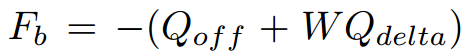
where 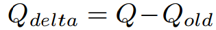 and
and 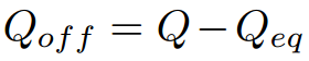 .
.
The Qeq is the desirable size of the queue, in other words, the desirable constant number of frames in the buffer. The Qdelta is the derivative of the number of elements in the queue and Qold is the number of elements in the queue when the last feedback message was sent. The Qoff represents the quantity of queue-size excess based on Qeq. W is a constant usually implemented as 2 and a good value for Qeq is know, by experience, to be 20 percent of the buffer size. The Feedback Value is a 6 bit-number and, if Fb is negative, a congestion is occurring and a feedback message is sent, otherwise, there are no congestion and any message is sent.
The RP algorithm
After receiving a feedback message, the source should react to reduce its transmission rate, and consecutively, the frame-loss rate at congestion situations. The reducion in transmission rate is also to allow the congestion point (the bottleneck switch of the path) to deal with all the frames presented in its buffers, and then, fix the congestion problem. Besides this first effect, after the solving the congestion, the algorithm must provide a mechanism to increase again the transmission rate. The RP will also count with a rate limiter(RL) control the bytes transmitted.
To explain the RP algorithm, some magnitudes must be defined. The CR will be the current transmission rate of the RL. The TR will be RL transmission rate just before the arrive of the last feedback message. The Byte Counter will be a counter presenting on the RP of the number of bytes transmitted. First, let the decreasing part of the algorithm be described. As told before, when a feedback message arrives, the transmission rate should be reduced. The CR and TR, will be updated as the following formulas.
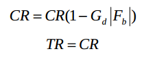
The constant Gd will be chosen as the multiplication of Gd for Fb would be at maximum 0.5. In other words, the maximum decreasing rate possible is dividing the transmission rate by a half.
The rate increasing process is divided in two subprocesses: the Fast Recovery and the Active Increase. Whenever a decreasing process occurs, the Byte Counter is cleared and the Fast Recovery states begin. This state has 5 cycles, each one corresponding for 150KB of data transmission. Whenever a cycle finishes, the CR is update by 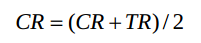
and the TR value remains the same. When the fifth cycles comes to an end, the Active Increase state begin. In this state, the RP will work through cycles of 75KB, and then, the values of TR and CR will be given as 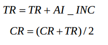
where AI_INC is a constant value of 5MBpS.
To improve the rate increasing efficiency, a Timer mechanism is used. The timer will work similarly to the Byte Counter, although they work in an independent manner. The method of updating the values of TR and CR will be defined by a combination of the states of the Timer and the Counter. If both the Timer and the counter be in the Fast Recovery State, the RP is on the Fast Recovery State. If only one of the objects be in the Active Increase state, the RP is in the Active Increase State. And at last, when both mechanisms are in the Hiper-Active State.